This sensor is ideally suited for threshold value measurement. This means that the sensor emits a digital high signal as soon as a threshold value set by the user on the rotary potentiometer is exceeded. It should be noted here that the digital signal is a comparison of the value set on the rotary potentiometer and the measured value on the sensor, which are then compared by the LM393 comparator installed on the board. The set value of the rotary potentiometer is the threshold value, which is used to define a logical high signal.
Digital output: If the sound level is above the set threshold value, a signal is output here
Analog output: Direct measured value of the sensor unit
LED1: Indicates that the sensor is supplied with voltage
LED2: Indicates that the sound level has exceeded the set threshold value
FUNCTIONALITY OF THE SENSOR
This sensor has two functional components on its circuit board: The front sensor unit, which physically measures the environment and outputs it as an analog signal to the second unit, the comparator. The comparator compares the measured value of the sensor with the value set on the rotary potentiometer and outputs a logical high signal on the digital pin and LED L1 if the value on the rotary potentiometer is exceeded.
Please note: The signal is inverted. If a high value is measured, this results in a lower voltage value at the analog output.
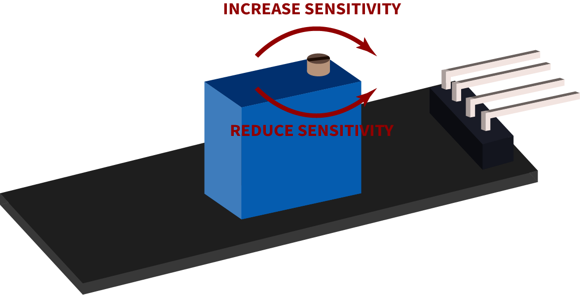
The rotary potentiometer can be set as follows:
PIN ASSIGNMENT


| ARDUINO | SENSOR |
|---|---|
| 5V | +V |
| GND | GND |
| Pin 3 | Digital Signal |
| Pin A0 | Analog Signal |
CODE EXAMPLE
The program reads the current voltage value, which can be measured at the analog output, and outputs it on the serial port. In addition, the status of the digital pin in the console is also indicated, which means whether the limit has been exceeded or not.
To load the following code example onto your Arduino, we recommend using the Arduino IDE. In the IDE, you can select the appropriate port and board for your device.
Copy the code below into your IDE. To upload the code to your Arduino, simply click on the upload button.
Related products
In stock


Electronics & Projects, Electronic Kits, IOT Kits, Starter Kits, Microcontrollers, Raspberry Pi, Pi 4, Pi Kits
Raspberry Pi 4 Desktop Kit – 2/4/8GB
€155.00 – €195.00 inc vat

Only 1 left in stock


 KY-038 Small Microphone Sound ...
€0.80 inc vat
In stock